Mini Dalek OLD STUFF
Hack #1 - This only applies to black PC board version 1.0
Servo Connection
You can optionally use this mod for remote dome rotation.
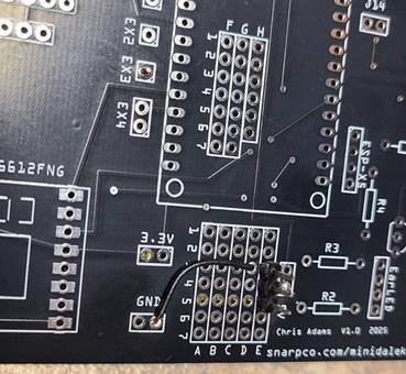
Version 1.0 of the PC board does not have a spot designated for the 3 pin servo connector.
I soldered a 3 pin connector in the proto area covering E3,E4 and E5.
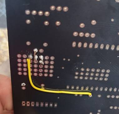
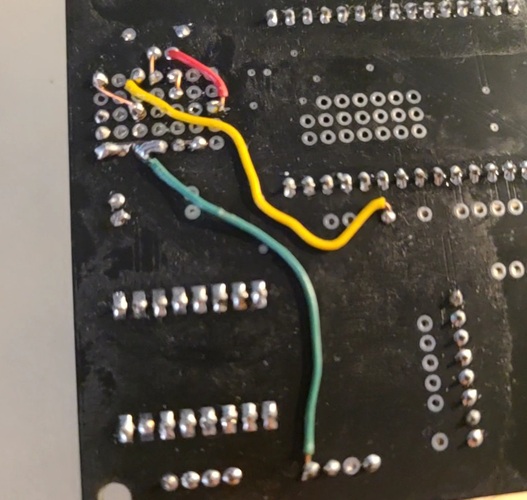
Run a wire on the top side from GND to D3. (black wire) USE A LONGER WIRE THAN I DID. YOU MAY HAVE TO MOUNT MORE COMPONENTS IN THIS AREA LATER
On bottom side bend the end of D3 wire and solder to E3.-à servo plug black or brown wire
On the bottom, run a wire from 5V to E4(center pin)-à servo plug red wire
(if your servo requires more than 5v, the center pin can be connected to an appropriate source)
On the bottom, run a wire from EX3 to E5(outer pin)(yellow wire)--à servo plug white or yellow
Hack #2 - This only applies to BLACK PC board version 1.0
Power connection and switch hack
I forgot to add a power switch. Up to this point I was plugging and unplugging the USB and AA batteries each time. This was very inconvenient and a risk to the delicate USB connection.
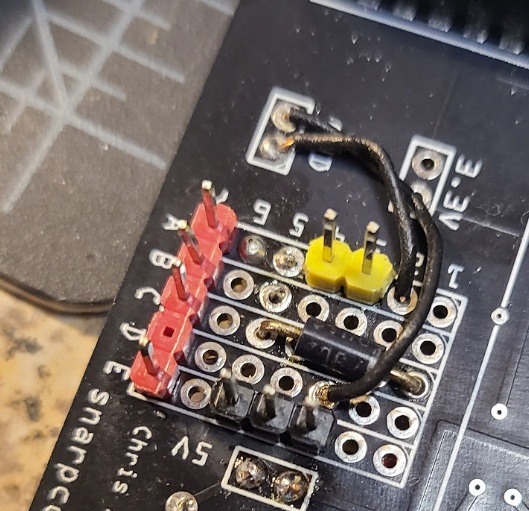
We are adding a 5 pin connector with pin 4 removed for 5v connection and a 2 pin connector for an SPST switch that will cut shared negative connection of the 2 power supplies. I am also adding a diode D1 to protect from reverse power connection.
Diode cathode (side with line) in C1.
Diode anode in C5.
2 pin connector in A3 and A4 (I used yellow)
5 pin connector with pin 4 removed in A7 thru E7 (I used red)
On bottom of board, connect wire from diode C7 to 5V (near 4E) (red wire)
On bottom of board, connect wire from pin 4 of motor power to A5 (green wire)
On the bottom, bridge A7,A6,A5,A4 with solder and a thin piece of wire (sorry)
On the bottom, connect E7 (pin 5) to diode C5
On top, connect wire from GND (near 6A) to A2, on bottom of board, bend wire and also solder to A3
Return to main MiniDalek site
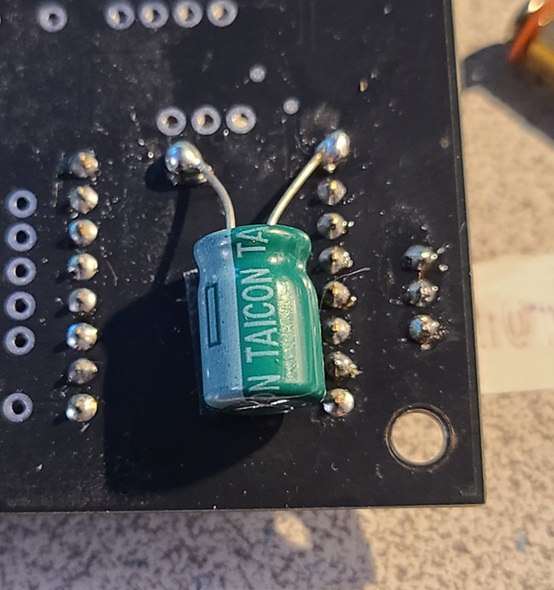
For black PC board V1.0
On bottom of PC board, scrape off some paint. Make sure that there are no traces where you are scraping.
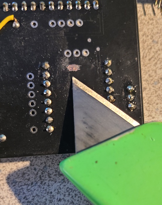
Tin the exposed copper with solder. Solder positive capacitor lead to pin 1 as pictured. Solder negative to your scraped area. Optionally use dab of E6000 or doublesided tape to hold it in place.